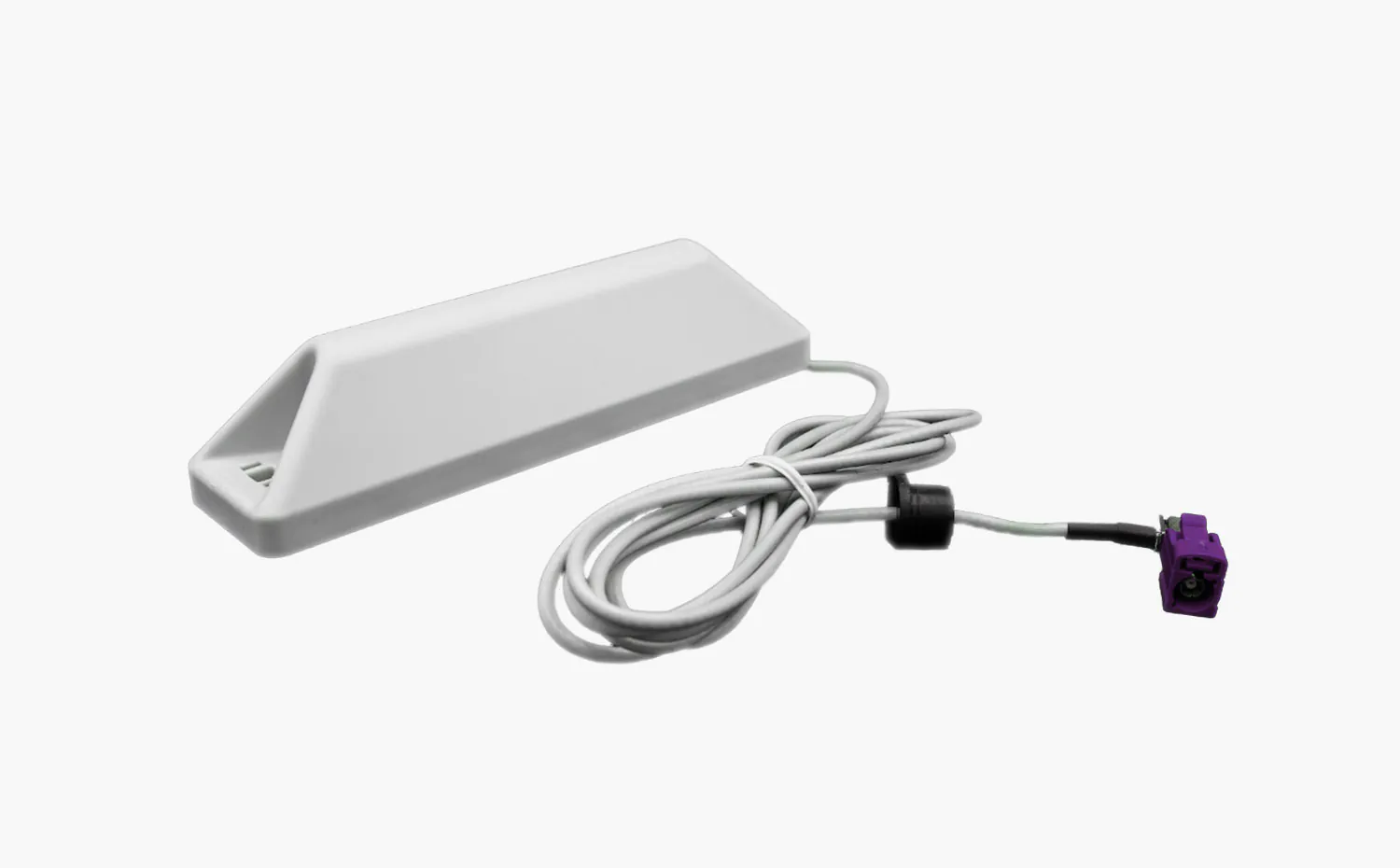
At the connection point, the connection between the antenna/device and the cable is made via a coaxial connector (read this article for more detailed information on the properties and variants of such connectors).
Coaxial cables can transmit high-frequency, broadband signals and are generally low-loss. They are used, for example, for broadcast signals, radar signals, or mobile radio signals. The following article deals with this special application.
Structure of antenna cables
Similar to antenna connectors, coaxial cables basically consist of four parts, which together determine the quality of the cable. The heart of every antenna cable is the inner conductor, which transports the mobile radio signal. The material used for this is usually copper, which is often silver-plated or tin-plated. Inner conductors can be rigid, or the flexible in the form of stranded wires. This core of the cable is surrounded by insulation material, the dialectic. It separates the inner conductor from the outer conductor and is usually made of plastic or even air.
The outer conductor provides electrical shielding from the outside environment and protects the inner conductor from interference signals. A coaxial cable can be single or double shielded.
As a final layer, each antenna cable has an outer jacket. This consists of a plastic layer and does not affect the electrical properties of the cable. Nevertheless, the jacket is important because it protects the cable from environmental influences. Important features here are, for example, the temperature range in which the cable can be used, or resistance to chemicals, fire and UV radiation.
Properties of antenna cables
One of the most important physical properties of coaxial cables is the characteristic impedance. This is characteristic for an antenna cable and is determined by the cable cross-section. The ratio between the diameter of the inner conductor and the inner diameter of the outer conductor is decisive here. In addition, the properties of the insulation material in the dialectic play a decisive role.
The impedance must be constant across any different cables and connectors used and is independent of the frequency. Accordingly, the required characteristic impedance must always be taken into account when selecting coaxial cables and connectors for connecting antennas and receivers. In mobile communications, this is classically 50Ω.
Also important is the attenuation, which indicates the signal loss when passing through the inner conductor. It is usually specified in decibels per meter and depends on the frequency to be transmitted: the higher it is, the higher the attenuation. In addition, the signal loss is determined by various factors that depend on the antenna cable. These include, first of all, the diameter of the inner conductor: thick coaxial cables are comparatively less lossy than thin ones, and are therefore usually preferred. Another factor is the nature and material of the conductor. For example, rigid conductors have lower loss than stranded conductors, and silver-plated copper has lower attenuation than pure copper. The age of the cable and the temperatures to which it is exposed also play a role.
Choosing the right cable variant in mobile communications
Which coaxial cable is the “best” depends on the individual application scenario. Among other things, the properties described above are decisive here: The impedance must be matched between cables and connectors. The attenuation depends on the frequency at which the mobile signal is to be transmitted. Attention must be paid to this when interpreting the manufacturer’s specifications.
Another selection criterion is the required length. This depends on the installation location. Basically, the shorter the cable, the lower the attenuation. At the same time, however, a short cable naturally goes hand in hand with a limited choice of location for the antenna.
In addition, the various coaxial cables differ in thickness: the larger the diameter, the better the shielding from interference signals and the lower the signal loss. However, thicker coaxial cables also have less mechanical flexibility, which can be a hindrance depending on the application scenario.
Last but not least, the price naturally also plays a role when selecting the right antenna cable. There can be big differences here between the different cable variants and manufacturers.
For LTE applications, common coaxial cables are, for example, the RG-316 U, the KXS-5, or the KXS-7. All of these cables have an impedance of 50Ω, which is typical for mobile communications.
The RG-316 U coaxial cable has a silver-plated stranded copper conductor as the inner conductor. The dialectic is made of PTFE plastic. The cable is single shielded by an outer conductor of silver plated copper braid. The outer sheath has a diameter of 2.5 mm. This makes the RG-316 U very flexible and uncomplicated to use, the minimum bending radius is only 15mm. However, the flexible inner conductor, the simple shielding and the small diameter are also accompanied by a higher attenuation: this is 0.8 db/m at a frequency of 800 MHz. For this reason, the cable is only suitable for short distances to the antenna of 1-2 meters maximum.
The KXS-5 is a so-called “low loss cable”. A rigid copper wire as inner conductor, a double shielding of a tinned copper braiding and an aluminum composite foil, as well as a larger diameter of 4.95 mm ensure here a comparatively low signal loss of 0.32 db/m at 800 MHz. This lower attenuation extends the recommended maximum cable length to 5-10 meters.
For even longer distances of maximum 10-20 meters between antenna and receiver, the KXS-7 cable is suitable. Here the inner conductor consists of a stranded copper wire, which is significantly thicker than the inner conductors of the other two cables. The double shielding is composed of a pure copper braid and a copper composite foil. The outer sheath has a diameter of 7.3 mm. This gives the cable the lowest attenuation of only 0.21 db/m at 800 MHz in this comparison.


